 Using Grids, Guides, Rulers and Measuring Tools
Grids, guides, rulers and the measuring tools assist in the editing, alignment and measurement of objects and document content.
Grids
Grids are used to line up objects and text in PDF documents. The grid is visible in the main window and displays over the document when it is enabled. Click the Show Grid icon in the View tab to enable the grid:
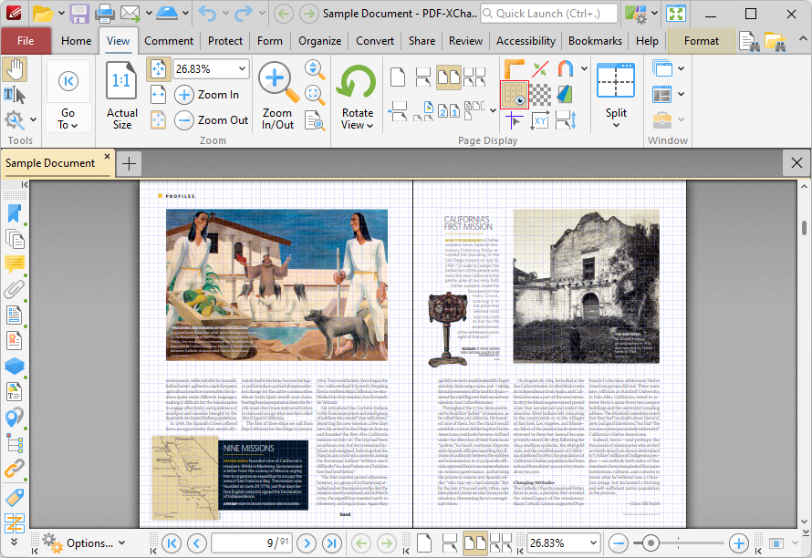
Figure 1. View Tab, Show Grid Highlighted, Grid Enabled
The Measurement preferences can be used to customize grids. Click the File tab, then click Preferences to open the preferences dialog box, and then click Measurement in the list of categories on the left:
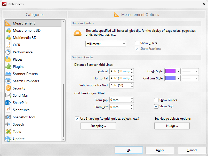
Figure 2. Preferences Dialog Box, Measurement Category Selected
•Use the Vertical and Horizontal dropdown menus to determine the distance between grid lines.
•Use the Subdivisions for Grid to determine how many subdivisions are contained in each box of the grid.
•Use the Grid Line Origin Offset dropdown menus to determine the offset of the starting point of the grid in relation to document pages.
•Select the Use Snapping box to enable snapping to grids.
•Click Snapping to customize snapping parameters:
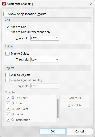
Figure 3. Customize Snapping Dialog Box
•Select the Show Snap location marks box as desired.
•Use the Grid settings to determine how objects in the document interact with grids:
•Select the Snap to Grid box to align objects with the nearest grid line when they are moved.
•Select the Snap only to Grids Intersections box to align objects to only the grid intersections.
•Select the Snap to Guides box to snap objects to guide lines when they are moved.
•Use the Threshold menu to determine the level of sensitivity for guide lines.
•Use the Objects settings to determine how snapping operates in conjunction with objects:
•Select the Snap to Objects box to enable snapping to objects.
•Select the Snap to Annotations Only box to enable snapping to only annotations and not other objects.
•Use the Threshold menu to determine the level of sensitivity for snapping to objects.
•Select the check boxes in the Snap to menu to determine at which points snapping is enabled for objects.
Rulers
Rulers can be used to check the size of document objects. Click the View tab, then click Show Rulers to enable/disable rulers:
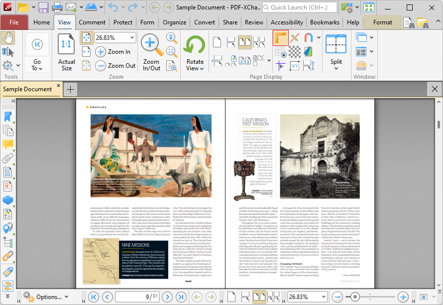
Figure 4. View Tab, Show Rulers Highlighted, Rulers Enabled
Rulers will then be displayed in the main window. Note that the Show Page Size/Position feature can be used in conjunction with rulers. This feature displays the coordinates of the current pointer location in the lower-left side of the user interface, which can be used to accurately place content and annotations and perform other editing operations:
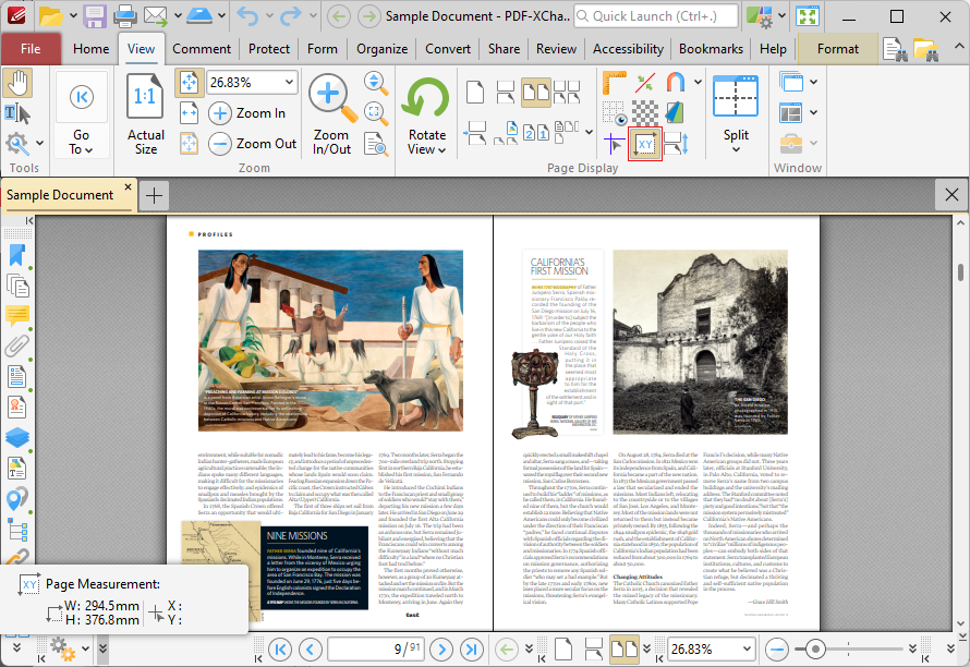
Figure 5. View Tab, Show Page Size/Position Feature and Output Highlighted
Note that the units of measurement used for rulers can be specified in the Measurement preferences.
Guides
Guides are used to assist in the accurate placement and lining up of document content and annotations. Click the View tab, then click Show Guides to enable/disable guides:

Figure 6. View Tab, Show Guides
When guides are enabled, click and drag from rulers to add guides to the document:
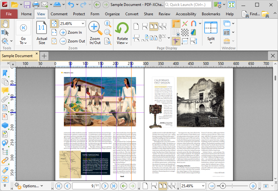
Figure 7. View Tab, Guides Added
If you want to delete a guide line, then select it and press the delete key. Right-click ruler margins for additional options:
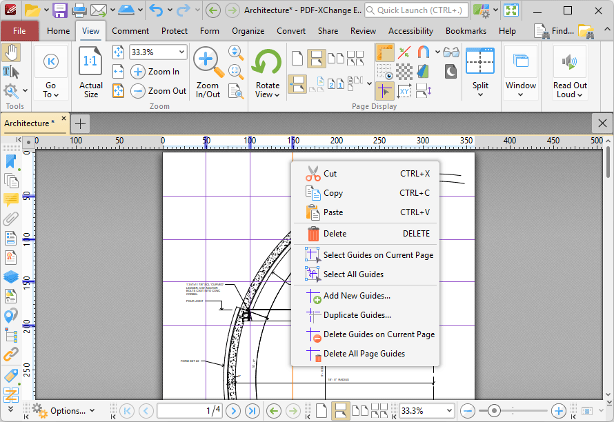
Figure 8. Guides Shortcut Menu
•Click Cut, Copy, Paste or Delete to perform these operations on selected guides.
•Click Select Guides on Current Page to select all guides on the current page of documents.
•Click Select All Guides to select all guides in documents.
•Click Add New Guides to add new guides to documents.
•Click Duplicate Guides to duplicate selected guides.
•Click Duplicate Guides on Current Page to duplicate guides on the current page.
•Click Duplicate All Page Guides to duplicate all page guides in the document.
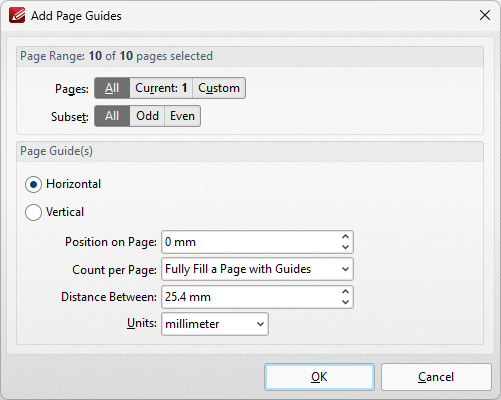
Figure 9. Add Page Guides Dialog Box
•Use the Page Range options to determine the pages to which new guides are added:
•Select All to specify all pages.
•Select Current to specify only the current page.
•Select Custom to specify a custom page range, then enter the desired page range in the adjacent number box. Further information about how to specify custom page ranges is available here.
•Use the Subset options to specify a subset of selected pages. Select All, Odd or Even as desired.
•Select Horizontal or Vertical to specify the type of guides you want to add to the document.
•Use the Position on Page dropdown menu to determine the position at which the guides are added.
•Use the Count per Page dropdown menu to determine how many guides are added to each page.
•Use the Distance Between dropdown menu to determine the distance between each guide.
•Use the Units dropdown menu to determine the units used in the Distance Between dropdown menu.
Click OK to add page guides to the document.
The Measuring Tools
The measuring tools are used to measure distances, perimeters and areas in documents. These tools can be used to indicate measurements in areas associated with objects in forms, computer-aided design (CAD) drawings and other similar documents. When the measuring tools are in use, the Measurement Information pane is displayed in the user interface, and it displays information about the current measurement. PDF-XChange Editor adds a pop-up note to completed measurements that details the value calculated:
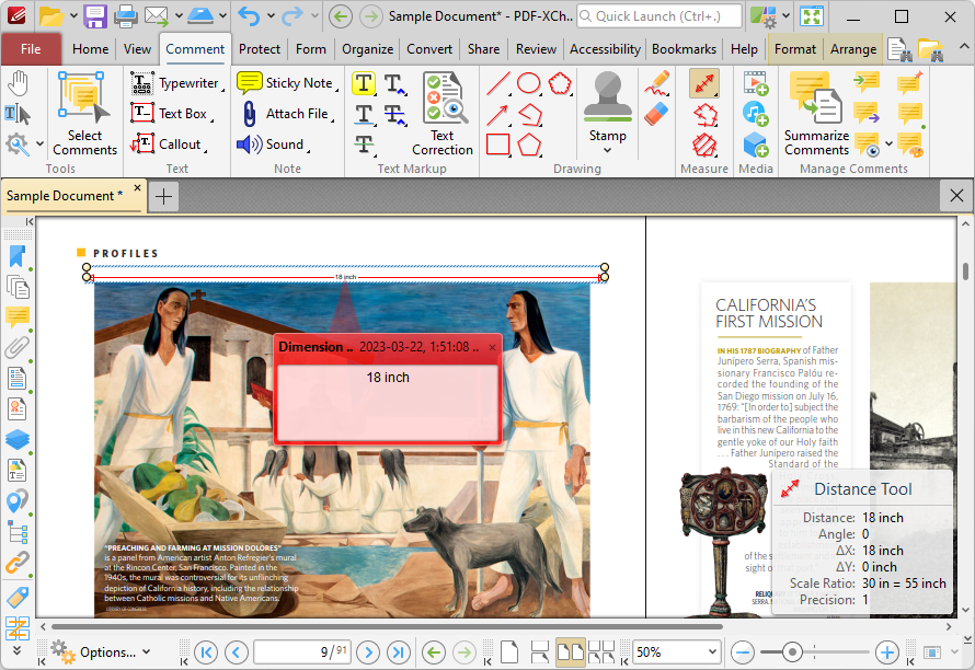
Figure 10. Example Measurement, Active Measurement Information Pane, Pop-Up Note Displayed
The Measuring Tools are available in the Comment tab:
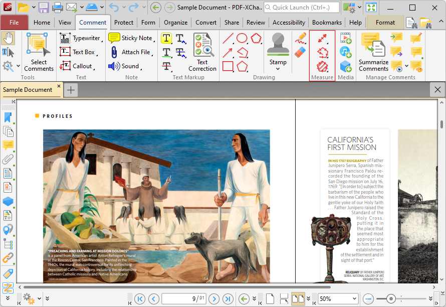
Figure 11. Comment Tab, Measuring Tools Highlighted
Using the Distance Tool
Click Distance Tool to measure the distance between two points:

Figure 12. Comment Tab, Distance Tool
When the Distance Tool is selected the pointer becomes a crosshairs icon. Click to start a measurement line. A red arrow will appear and the Distance Tool information box will be displayed in the lower right corner of the active window. Drag the crosshairs to the desired point, then click to determine the distance measured. The baseline is then established. The distance from the start point will be displayed as the pointer is moved, and further details will be displayed in the information box. Click again to set the baseline as the final measured distance. Alternatively, move the pointer up/down to reposition the baseline at a parallel position within the document and create perpendicular leader lines at either end. Click to complete the process:
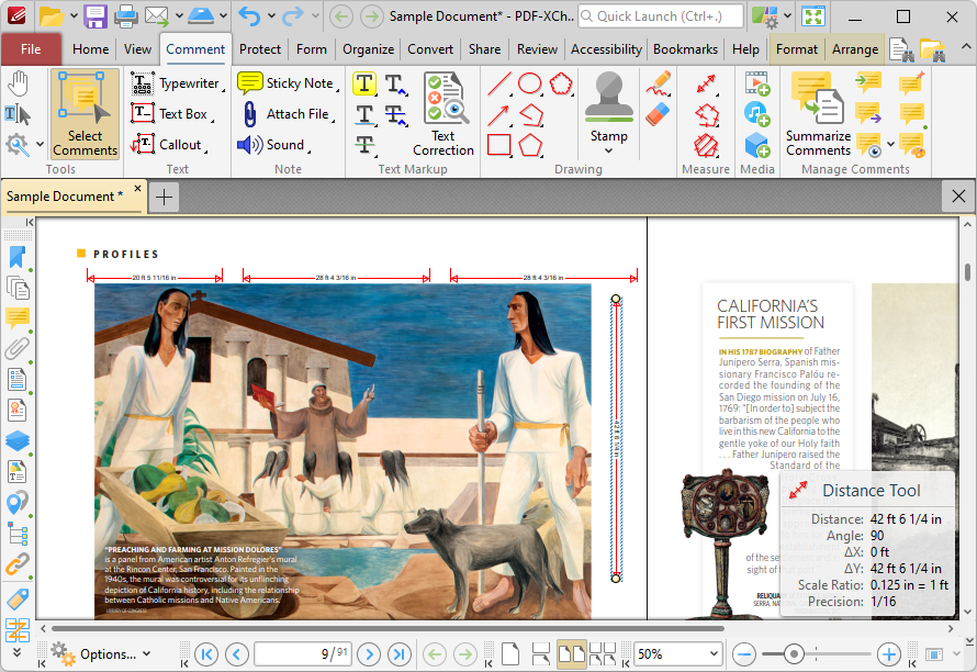
Figure 13. Distance Tool Examples
•The Distance Tool calculates and displays distances measured according to the active scale, which can be determined in the Format tab, as detailed below.
•Right-click lines and select Open Pop-Up Note to customize the scale reference figure in the pop-up note.
•Click and drag the control points at either end of the baseline to adjust the length of the adjoining perpendicular lines.
•Click and drag the second pair of control points to adjust the length of the baseline and the angle of the annotation.
•Click and drag to reposition lines.
•Use the arrow keys to reposition lines. Hold down Shift to move at an increased increment.
•Hold down Shift to create lines at increments of fifteen degrees.
•Right-click lines for further editing options. See here for an explanation of these options.
•Press Ctrl+' to open the Properties pane for selected lines and view/edit properties.
Using the Perimeter Tool
Click Perimeter Tool to measure the distance between multiple points:

Figure 14. Comment Tab, Perimeter Tool
When the Perimeter Tool is selected the pointer becomes a crosshairs icon. Click to start a perimeter line. A red line will appear and the Perimeter Tool information box will be displayed in the lower right corner of the active window. This box will update as the tool is used. Drag the crosshairs to the desired location and click again to define the first line of the perimeter. Repeat the process until the perimeter is complete and then double-click to set the final point:
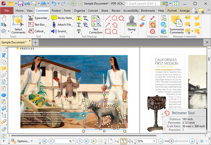
Figure 15. Perimeter Tool Example
•The Perimeter Tool calculates and displays distances measured according to the active scale, which can be determined in the Format tab, as detailed below.
•Click and drag the perimeter line to reposition it. The circle at the center can also be used for this purpose.
•Click and drag the outer control points to resize the perimeter line.
•Click and drag the inner control points to reshape the perimeter line.
•Click and drag the green control point at the top to rotate the perimeter line. Hold down Shift to rotate at increments of fifteen degrees.
•Use the arrow keys to reposition perimeter lines. Hold down Shift to move at an increased increment.
•Hold down Shift to create perimeter lines at increments of fifteen degrees.
•Right-click perimeter lines for further options. See here for an explanation of these options.
•Press Ctrl+' to open the Properties pane for selected perimeter lines and view/edit properties.
Using the Area Tool
Click Area Tool to measure custom document areas:
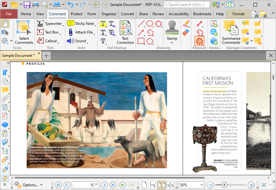
Figure 16. Comment Tab, Area Tool
When the Area Tool is selected the pointer becomes a crosshairs icon. Click to start an area measurement. A red line will appear and the Area Tool information box will be displayed in the lower right corner of the active window. This box will update as the tool is used. Drag the crosshairs to the location to which the first measurement is to be made, then click again to set the first line of the area measurement. Repeat the process until the area is complete and then double-click to define the final point:
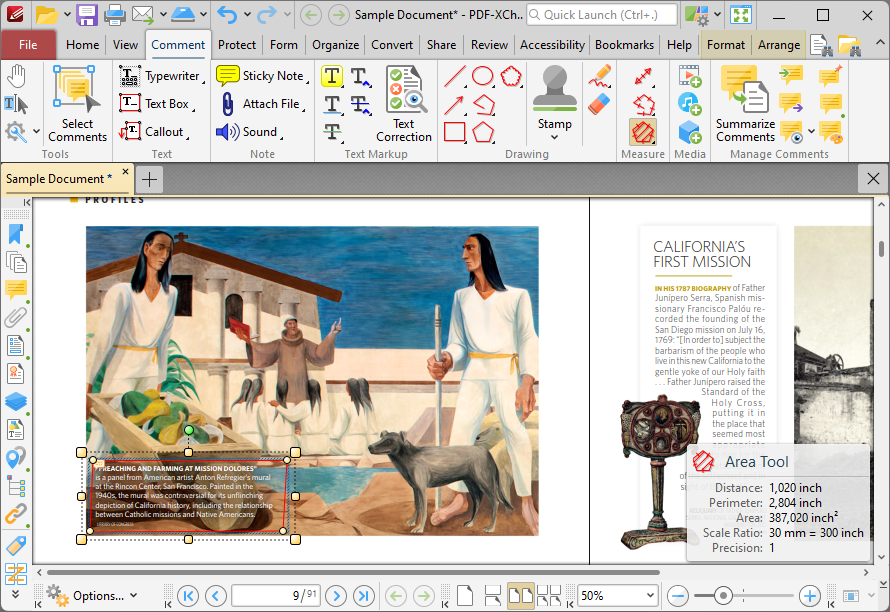
Figure 17. Area Tool Example
•The Area Tool calculates and displays areas measured according to the active scale, which can be determined in the Format tab, as detailed below.
•Click and drag the area annotation to reposition it. The circle at the center can also be used for this purpose.
•Click and drag the outer control points to resize the area annotation.
•Click and drag the inner control points to reshape the area annotation.
•Click and drag the green control point at the top to rotate the area annotation. Hold down Shift to rotate at increments of fifteen degrees.
•Use the arrow keys to reposition area annotations. Hold down Shift to move at an increased increment.
•Hold down Shift to create area annotations at increments of fifteen degrees.
•Right-click area annotations for further options. See here for an explanation of these options.
•Press Ctrl+' to open the Properties pane for selected perimeter lines and view/edit properties.
Using the Format Tab for Measuring Tools
Note that when one of the Measuring Tools are enabled, the Format tab is available and can be used to customize the default properties of annotations:
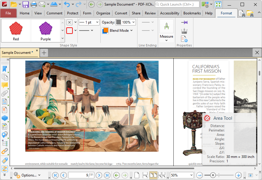
Figure 18. Format Tab, Distance Tool
•Use the options in the Shape Style group to determine the color, border, opacity and blend mode of annotations.
•Use the options in the Line Ending group to determine the style used at the start and end of annotations.
•Use the options in the Measure group to determine the scale used for annotations, or to set new scales, as detailed below.
•Click Export to CSV to export the document to a comma-separated-values document.
•Click Keep Selected to keep the tool selected and create multiple annotations consecutively. If this option is disabled then PDF-XChange Editor will revert to the designated default tool after the creation of one annotation.
•Click Exclusive Mode to give the tool priority over all other document content. When Exclusive Mode is enabled, the pointer ignores all interactive elements of documents other than base content. This makes it possible to create annotations on areas that overlap with other content without the risk of accidentally selecting undesired items. When Exclusive Mode is disabled, the pointer recognizes and interacts with all content as normal.
•Click Properties to view/edit the tool properties.
When annotations are selected, additional options are available in the Format tab:
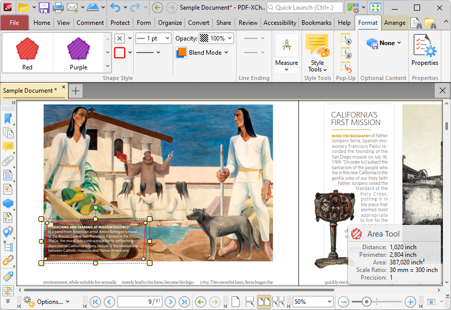
Figure 19. Format Tab for Selected Annotations
•The Style Tools dropdown menu is available in the Format tab. It contains the following options:
•Click Copy Comment Style to copy the style properties of annotations.
•Click Apply Copied Comment Style to apply a copied annotation style to selected annotations.
•Click Apply Copied Comment Appearance to apply a copied annotation appearance to selected annotations.
•Click Make Current Properties Default to set the properties of the annotation as the default properties for subsequent annotations of the same type.
•Click Apply Default Properties to apply the default annotation properties to selected annotations.
•Use the options in the Pop-up group to interact with the pop-up note of selected annotations:
•Click Open to open the pop-up note.
•Click Hide to hide the pop-up note.
•Click Reset Location to reset the location of the pop-up note.
•Click Edit Label to create/edit the text label of the annotation, or click Delete Label to delete the label. Note that labels are displayed when the pointer is hovered over the annotation.
When annotations are selected, the Arrange tab is also available and can be used to manipulate comments as detailed here.
Note that the Comment Styles Palette can be used to edit and save customized annotation styles for subsequent use, and the Commenting preferences can be used to view/edit preferences for all comments.
Setting Scales
When the Measuring Tools are selected, click Measure in the Format tab, then click Scale to view/select/manage/calibrate scales:
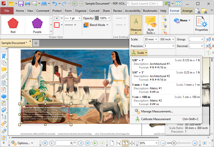
Figure 20. Format Tab, Scale Options
The following options are available:
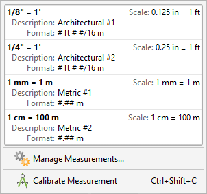
Figure 21. Scale Options
•Click to activate existing scales.
•Click Manage Measurements to view/edit/clone/delete/import/export scales.
•Click Calibrate Measurement to calibrate a new measurement. The pointer will become a crosshairs icon. Click and drag to determine a calibration distance. The Calibration dialog box will open:
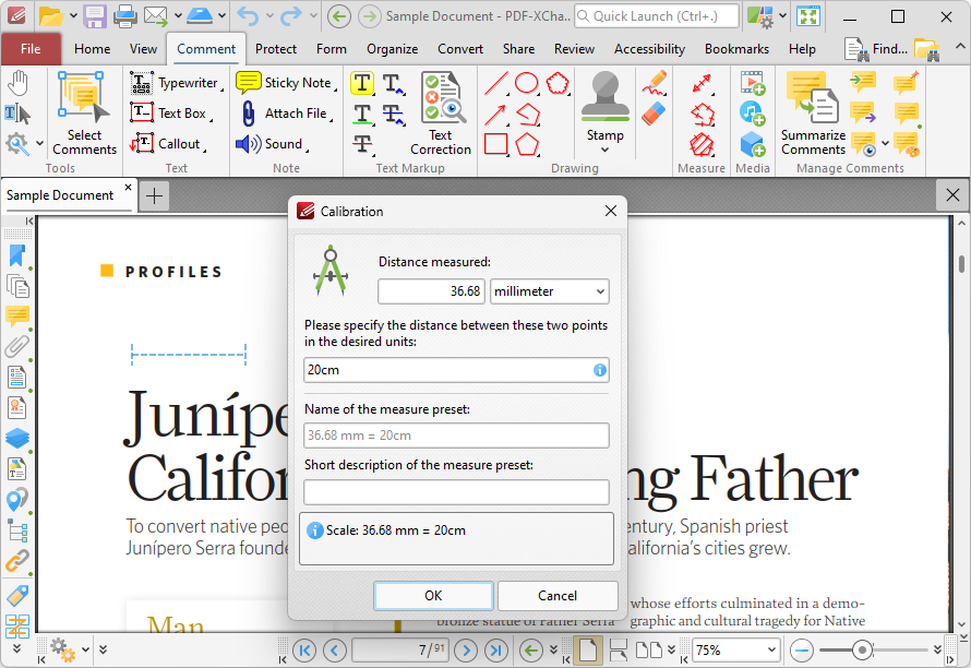
Figure 22. Calibration Dialog Box
•The distance determined in the document is detailed in the upper number box. Use the dropdown menu to select the desired units of measurement.
•Use the lower number box to determine the scale. Enter a numerical value and the desired units of measurement for the scale.
•Name and describe the calibration. The scale will be detailed in Scale pane.
Click OK to save the calibration.
The keyboard shortcut to enable this feature is Ctrl+Shift+C.